FEATURES AND BENEFITS:
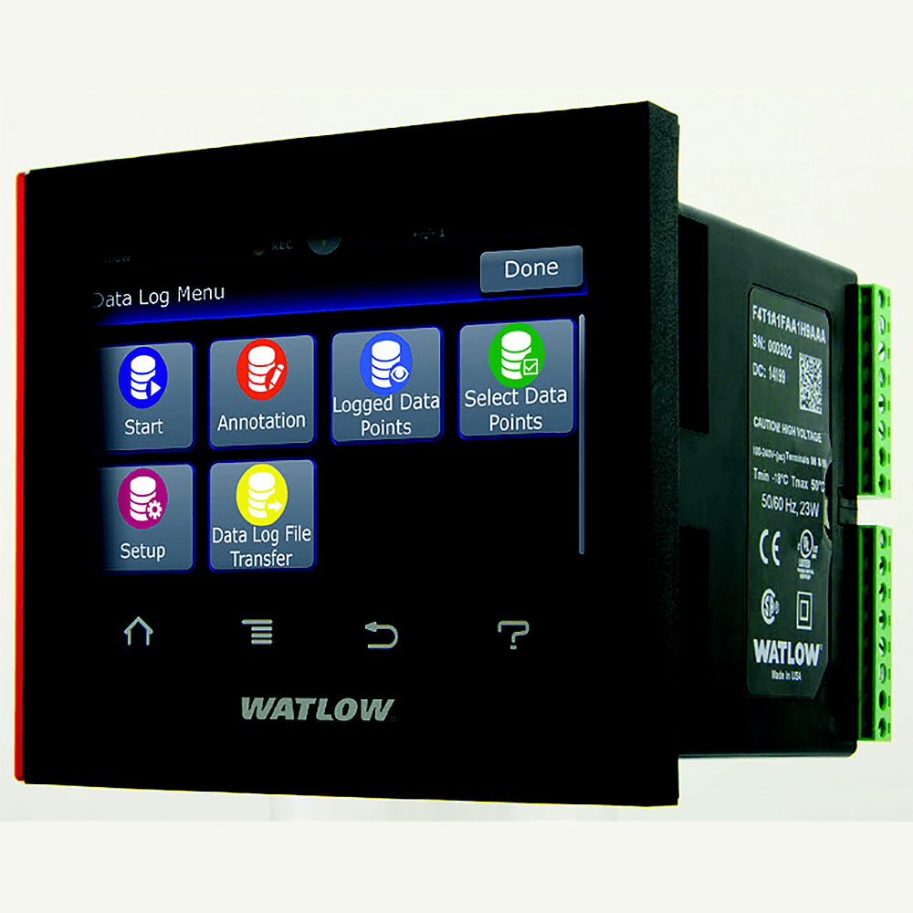
4.3-inch, color touch panel with high-resolution, graphical user-interface
- Shortens learning curve and reduces operator errors
- Allows channels, alarms, inputs and outputs to be personalized with user defined names
- Intuitive screens layout and menu navigation
- Programmable to show information in multiple languages
Data Logging
- Easily complies with regulatory standards with ability to choose encrypted, .CSV or both types of file formats for tamper proof record needs
- Enables security using lock-out security levels for different user groups
- Simplifies record keeping management with ability to archive records to the cloud or a connected PC network
- Flexibility to select which parameters to log from one to up to 128 points simultaneously
- Choose where you want to store the files—inside the controller, on a connected USB memory device, or to a connected PC anywhere in the world
- Record as fast as one time per 0.1 second or as slow as one time per hour
1 to 24 Channel Data Logger
- Scalable channels, pay for only what you need
- Compatible with temperature, altitude, humidity, AC current and other 0-10VDC or 0-20mA process units
- Flexibility to meet diverse process applications
- Field expandable channels and I/O if application needs grow in the future
Trend Screens
- Create up to four unique trend graph screens
- Graph any input sensor or process value
COMPOSER® graphical configuration PC software
- Speeds up and simplifies commissioning
- Archives and documents controller setup
- Connects with controller easily via Ethernet
Many communications options available including Ethernet, Modbus® TCP and SCPI and EIA-232/485 Modbus® RTU
- Offers two USB host ports and one device port
- Simplifies methods to manually or automatically archive data log files to cloud or PC
- Easily connect and transfer data log or configuration set up files
Modular design
- Adapts quickly to evolving requirements
- Offers numerous types of field pluggable modules for maximum flexibility and easiest compatibility
- Features scalable and modular firmware functions
- Delivers scalable input/output quantities from 1 to 24
Agency certifications include UL®, FM, CE, RoHS, W.E.E.E., NEMA 4X/IP65
- Ensures high quality and reliability
- Verifies performance in installations worldwide
Off-the-shelf solution
- Provides cost-effective “make versus buy”
- Offers preconfigured touch-panel screens
- Assures quicker time to market
MODEL NUMBER GUIDE:
| D | 4 | T | 1 | __ | __ | __ | __ | __ | __ | __ | 5 | __ | __ | __ |
| 1 | 2 | 3 | 4 | 5 | 6 | 7 | 8 | 9 | 10 | 11 | 12 | 13 | 14 | 15 |
| 1-3. Controller Style | ||
| D4T = Base includes: 4.3 inch color graphical touch panel, standard bus communications, Ethernet Modbus TCP and SCPI protocol. | ||
| 4. Application Type | ||
| 1 = Standard | ||
| 5. Data Logging (choose J, K, L or M) | ||
| J = Data logging | ||
| K = Data logging with encrypted files | ||
| L = Data logging with graphical trend charts | ||
| M = Data logging with encrypted files and graphical trend charts | ||
| 6. Power Supply Connector & Voltage, Logo (choose 1, 2, 3, 4, 5, 6, 7 or 8) | ||
| Power Supply & Logo |
Power Supply Connector
|
|
| 1 = 100 to 240VAC with Logo |
Right angle (standard)
|
|
| 2 = 100 to 240VAC without Logo |
Right angle (standard)
|
|
| 3 = 100 to 240VAC with Logo |
Front screw
|
|
| 4 = 100 to 240VAC without Logo |
Front screw
|
|
| 5 = 24 to 28VAC or VDC with Logo |
Right angle (standard)
|
|
| 6 = 24 to 28VAC or VDC without Logo |
Right angle (standard)
|
|
| 7 = 24 to 28VAC or VDC with Logo |
Front screw
|
|
| 8 = 24 to 28VAC or VDC without Logo |
Front screw
|
|
| 7. Function Blocks (choose A, B or C) | ||
| A = Basic Set | ||
| B = Set 1 | ||
| C = Set 2 | ||
| NOTE: Refer to the D4T spec sheet “Number of Function Blocks by Ordering Option” in the specifications section for quantities and types of function blocks in each set. | ||
| 8-9. Communication Options | ||
| AA = Modbus TCP (Ethernet) | ||
| A3 = EtherNet/IP | ||
| 10-11. Documentation, Accent Bar, Replacement Connectors (choose 1A, 1B, 1C, 1D, 1E, 1F, 1G, 1H or 1J) | ||
|
Documentation DVD / QSG
|
Decorated Brushed Aluminum Accent Bar
|
|
| 1A = Yes |
Gray
|
|
| 1B = Yes |
Blue
|
|
| 1C = Yes |
Red
|
|
| 1D = Yes |
None
|
|
| 1E = No |
Gray
|
|
| 1F = No |
Blue
|
|
| 1G = No |
Red
|
|
| 1H = No |
None
|
|
| 1J = Replacement connectors only – for the model number entered | ||
| 12. Additional Options | ||
| 5 = None | ||
| 13-14. Number of Logging Channels & Input Hardware Types | ||
| Universal Input(s) (T/C, RTD 2-wire or 3-wire, 0-10VDC, 0-20mA) | ||
| U1 = 1 Channel | ||
| U2 = 2 Channels | ||
| U3 = 3 Channels | ||
| U4 = 4 Channels | ||
| U5 = 5 Channels | ||
| U6 = 6 Channels | ||
| Thermistor Input(s) | ||
| T1 = 1 Channel | ||
| T2 = 2 Channels | ||
| T3 = 3 Channels | ||
| T4 = 4 Channels | ||
| T5 = 5 Channels | ||
| T6 = 6 Channels | ||
| Universal Input(s) (T/C, RTD 2-wire, 0-10VDC, 0-20mA) | ||
| 04 = 4 Channels | ||
| 08 = 8 Channels | ||
| 12 = 12 Channels | ||
| 16 = 16 Channels | ||
| 20 = 20 Channels | ||
| 24 = 24 Channels | ||
| Thermistor Input(s) | ||
| TA = 4 Channels | ||
| TB = 8 Channels | ||
| TC = 12 Channels | ||
| TD = 16 Channels | ||
| TE = 20 Channels | ||
| TF = 24 Channels | ||
| 15. Number of Auxiliary/Alarm Outputs, Digital Inputs & Hardware | ||
| NOTE: Options below are not available with 6 or 24 channel input models – U6, T6, 24, TF. | ||
| A = None | ||
| Single Output | ||
| C = 1 switched dc/open collector | ||
| E = 1 mechanical relay 5A, Form C output | ||
| F = 1 universal process/retransmit | ||
| Multiple Digital Inputs/Outputs | ||
| D = 6 digital I/O | ||
| P = 3 universal process/retransmit outputs | ||
| B = 3 mechanical relay 5A, 2 Form C and 1 Form A (Form A shares a common with 1 Form C) | ||
| J = 4 mechanical relay 5A, Form A | ||
| K = 2 SSRs Form A, 0.5A | ||
| T* = 2 SSRs at 10A | ||
| L = 4 SSRs at 2A each, SSRs grouped in 2 pairs with each pair sharing a common. | ||
| Communications | ||
| M= Modbus RTU 232/485 | ||
| * Option “T” not available with digit 13 & 14 options U5, U6, T5, T6, 20, 24, TE and TF. | ||